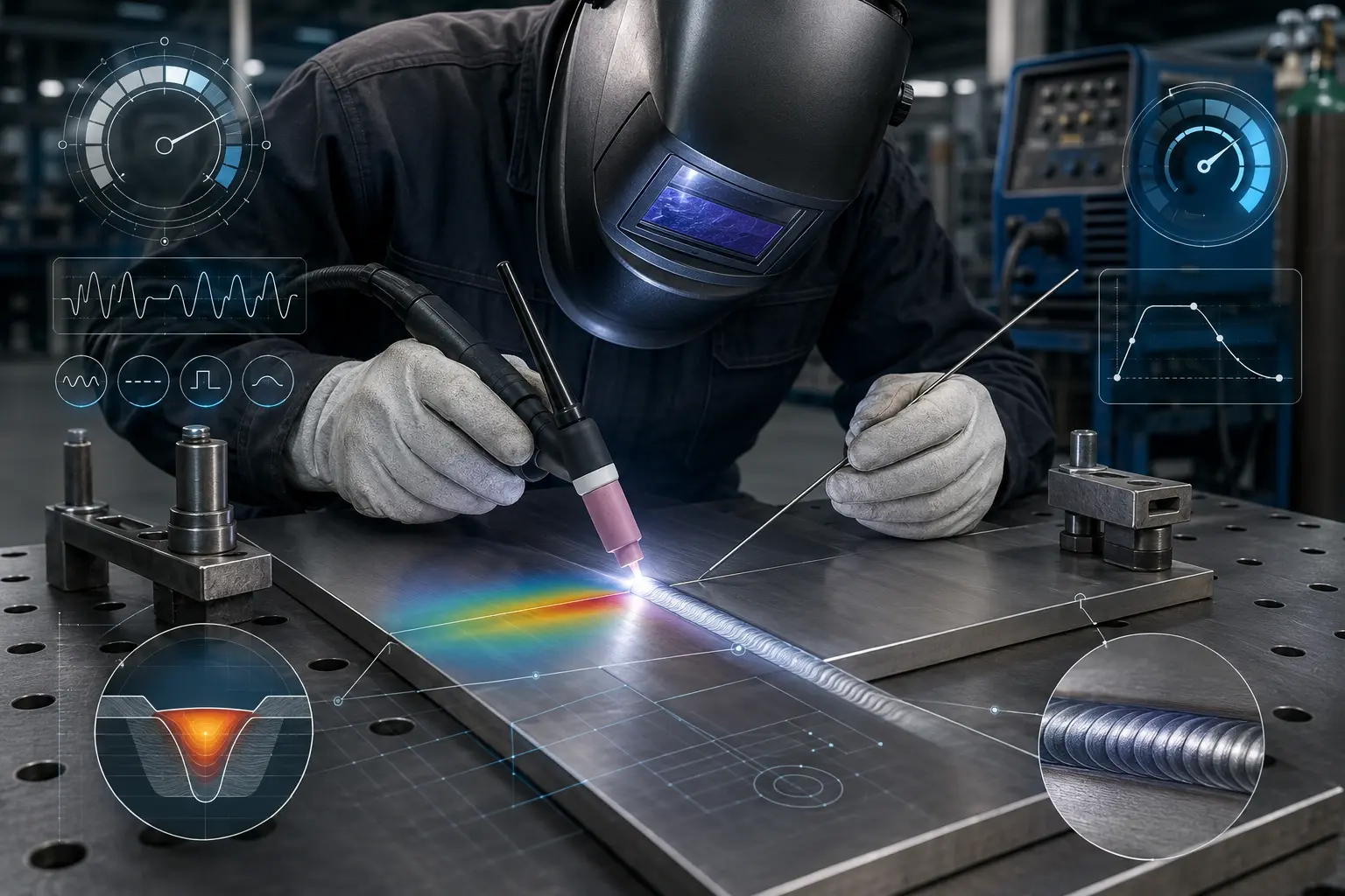
Stainless Steel Welding Parameters: 304, 316L, 2205 and 2507 by Thickness
If you remember one thing from this guide, make it this: keep your interpass temperature below 150°C, control your heat input, and protect the root side of the weld when corrosion resistance matters.
Most stainless steel welding problems do not come from one dramatic mistake. They usually come from small errors repeated throughout the job: too much heat, poor gas coverage, contaminated joint preparation, or an unprotected root side. The result may look acceptable at first, but the weld can lose corrosion resistance, crack during service, or fail inspection later.
The welding parameters below are practical starting points for TIG and MIG welding. Your exact settings may shift by 5–10% depending on the machine, joint design, welding position, fit-up, shielding gas, filler metal, and operator technique. Always run a test bead on matching scrap before welding the actual part.
Important note: These values are general workshop starting points, not a replacement for a qualified WPS, PQR, project specification, filler metal datasheet, or applicable welding code. For pressure vessels, food equipment, chemical piping, marine components, and critical load-bearing structures, follow the approved procedure first.
Stainless Steel Welding Parameters for 304, 316L, 2205 and 2507
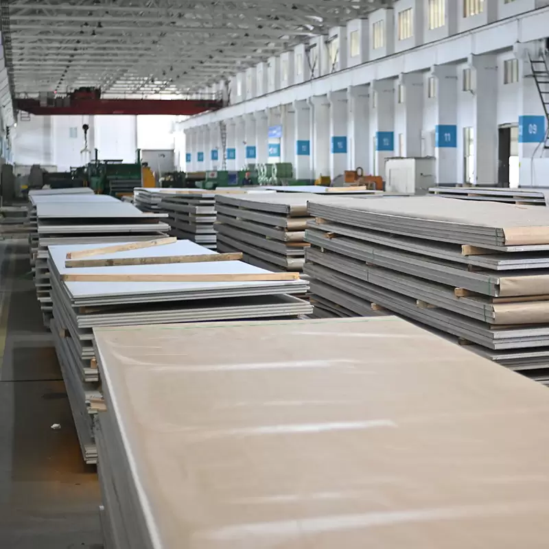
304 and 304L are the most common austenitic stainless steels used in fabrication. They offer good weldability, stable arc behavior, and a forgiving heat input window compared with duplex grades. However, many shops still run 304 too hot because they treat it like mild steel.
Stainless steel holds heat longer than carbon steel. As a starting rule, use about 10% fewer amps than you would use on carbon steel of the same thickness, then adjust based on bead appearance and penetration.
| Thickness | Process | Amps | Volts | Wire | Tungsten | Gas Flow |
|---|---|---|---|---|---|---|
| 1.0–2.0 mm | TIG | 50–80 A | — | ER308L | 2.4 mm | 8–10 L/min |
| 3.0–5.0 mm | TIG | 90–130 A | — | ER308L | 3.2 mm | 10–12 L/min |
| 6.0–8.0 mm | TIG | 140–180 A | — | ER308L | 4.0 mm | 12–15 L/min |
| 1.6 mm | MIG pulsed | 90 A | 20 V | ER308LSi, 1.0 mm | — | 20–25 L/min |
| 3.2 mm | MIG short arc | 135 A | 21 V | ER308LSi, 1.2 mm | — | 20–25 L/min |
| 4.8 mm | MIG spray transfer | 175 A | 29 V | ER308LSi, 1.0 mm | — | 20–25 L/min |
For TIG welding, a useful starting formula is 1 amp per 0.001 inch of material thickness. For example, 0.062 inch stainless sheet can start around 60–65 amps, then be adjusted based on joint fit-up and bead shape.
For MIG welding 304 stainless steel, use argon with 1–2% CO₂ and ER308LSi wire. The added silicon in ER308LSi improves puddle fluidity and bead wetting. For TIG welding, ER308L filler and 2% lanthanated tungsten are common choices.
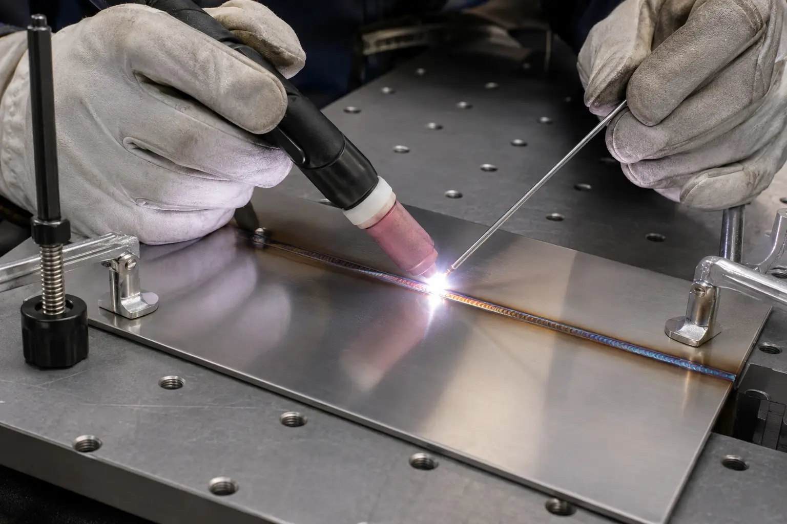
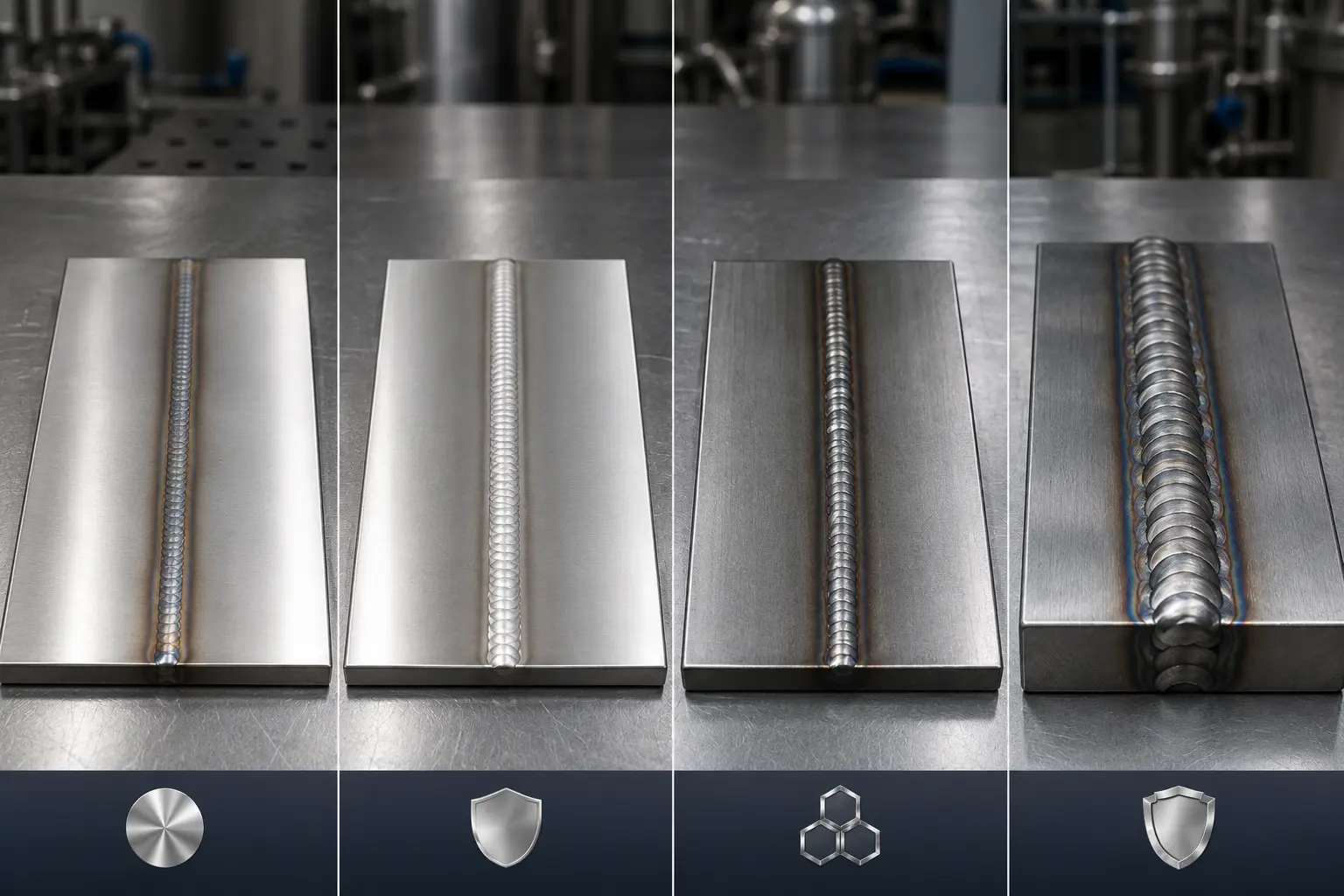
A shiny or light straw-colored bead is usually a good sign. A blue, gray, or black bead usually means too much heat, poor shielding gas coverage, excessive stick-out, drafts near the weld zone, or insufficient post-flow.
316/316L Stainless Steel — Similar Settings, Stricter Root Protection
For most workshop applications, TIG and MIG welding parameters for 316 and 316L are very close to 304. The amperage, travel speed, and shielding gas flow usually do not require major changes. The more important difference is corrosion performance.
316L contains molybdenum, which improves resistance to chloride corrosion. That is the reason many buyers choose 316L over 304 for marine, chemical, food processing, pharmaceutical, and outdoor environments. If the weld root is heavily oxidized, that advantage can be reduced or lost.
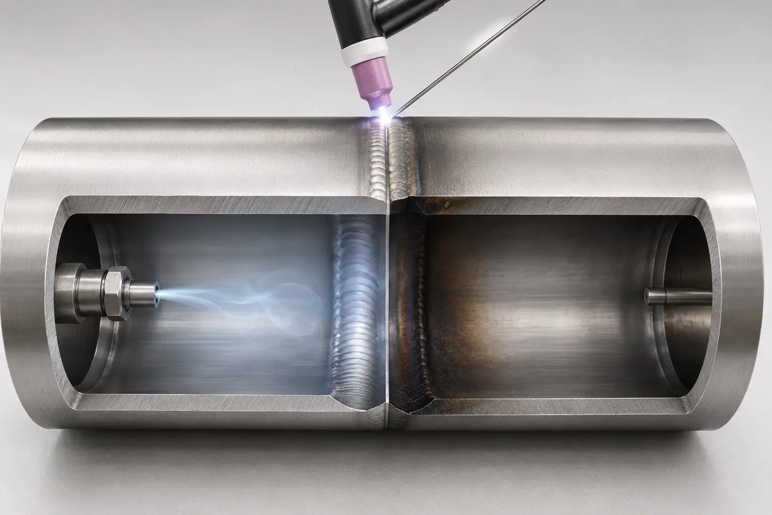
Back purge guidance: For full-penetration 316L welds where the root side remains exposed to service conditions, back purging is strongly recommended and often mandatory by procedure. Without root shielding, the back side can form heavy oxidation, commonly called sugaring, which reduces corrosion resistance.
Use high-purity argon for back purging. A common starting range is 5–10 L/min, approximately 10–20 CFH. Continue purging until the weld zone has cooled enough to avoid root oxidation. If the root side is dark, crusty, or heavily oxidized instead of clean silver or light straw, the purge protection was not sufficient.
- TIG filler: ER316L
- MIG wire: ER316LSi
- TIG shielding gas: 100% argon, usually 8–15 L/min depending on cup size
- MIG shielding gas: argon with 1–2% CO₂
- Interpass temperature: keep below 150°C unless the approved procedure says otherwise
Duplex 2205 Stainless Steel — Tight Heat Input Window
2205 duplex stainless steel is stronger than 304 and 316L and offers better chloride pitting resistance. That performance depends on its balanced austenite-ferrite microstructure. Welding parameters must preserve that balance.
The typical heat input window for 2205 is 0.5–1.5 kJ/mm. If heat input is too low, the weld can retain excessive ferrite and become less tough. If heat input is too high, harmful intermetallic phases may form and reduce toughness and corrosion resistance.
Heat Input Formula
Heat Input (kJ/mm) = (Amps × Volts × 60) / (Travel Speed mm/min × 1000)
Example: at 120 A, 12 V, and 80 mm/min travel speed:
(120 × 12 × 60) / 80,000 = 1.08 kJ/mm
This value sits within the recommended window for 2205 welding.
TIG Welding Parameters for 2205 Duplex Stainless Steel
| Thickness | Amps | Volts | Travel Speed | Heat Input | Filler |
|---|---|---|---|---|---|
| 1.5 mm | 70–90 A | 10–12 V | 90–120 mm/min | 0.5–0.8 kJ/mm | ER2209 |
| 3.0 mm | 100–130 A | 11–13 V | 70–100 mm/min | 0.7–1.1 kJ/mm | ER2209 |
| 6.0 mm | 140–170 A | 12–14 V | 50–75 mm/min | 0.9–1.4 kJ/mm | ER2209 |
ER2209 filler is commonly used for 2205 because it is over-alloyed with nickel to help restore the austenite-ferrite balance after welding. For MIG welding, 0.8–1.2 mm ER2209 wire can be used with argon plus 1–2% CO₂, while keeping the same heat input requirement.
Interpass temperature is critical. Keep it below 150°C. In duplex welding, an infrared thermometer is not optional workshop decoration; it is part of process control. Check between passes, especially on thicker plate and multi-pass welds.
2507 Super Duplex Stainless Steel — Higher Alloy, Smaller Margin for Error
2507 super duplex stainless steel contains higher chromium and molybdenum than 2205. It is used when chloride exposure is too severe for standard duplex stainless steel. Typical applications include seawater systems, desalination equipment, chemical processing, offshore structures, and high-chloride heat exchangers.
The welding logic is similar to 2205: control heat input, protect the root side, use the correct filler, and keep the interpass temperature below 150°C. The difference is that 2507 has an even smaller margin for error. Overheating, slow cooling, or poor shielding can damage the phase balance and reduce corrosion performance.
TIG Welding Parameters for 2507 Super Duplex Stainless Steel
| Thickness | TIG Amps | Filler | Interpass Limit | Notes |
|---|---|---|---|---|
| 1.5–3.0 mm | 60–110 A | ER2553 | ≤150°C | Use fast travel and avoid excessive heat buildup. |
| 3.0–6.0 mm | 100–150 A | ER2553 | ≤150°C | Maintain heat input within the approved range. |
| 6.0–12.0 mm | 140–200 A | ER2553 | ≤150°C | Use multi-pass control, strict purge protection, and interpass checks. |
For MIG welding 2507, ER2553 wire is commonly used under argon with 1–2% CO₂. Amperage may range from approximately 80–300 A depending on thickness, wire diameter, transfer mode, and joint design. As with 2205, the exact welding procedure should be controlled by heat input rather than amperage alone.
Grade Comparison at a Glance
| Item | 304/304L | 316/316L | 2205 Duplex | 2507 Super Duplex |
|---|---|---|---|---|
| TIG Filler | ER308L | ER316L | ER2209 | ER2553 |
| MIG Wire | ER308LSi | ER316LSi | ER2209 | ER2553 |
| Back Purge | Recommended for full penetration | Strongly recommended or required for exposed roots | Required for critical welds | Required for critical welds |
| Heat Input Control | Moderate control | Moderate control | 0.5–1.5 kJ/mm typical range | 0.5–1.5 kJ/mm typical range |
| Interpass Temperature | ≤150°C | ≤150°C | ≤150°C | ≤150°C |
| Welding Difficulty | Low | Moderate | High | High |
| Cost of Getting It Wrong | Rework or appearance defects | Corrosion failure | Loss of toughness or corrosion resistance | Severe corrosion or service failure |
Before You Strike the Next Arc
Before welding stainless steel, check these three things. They are simple, but they prevent most common weld defects.
1. Confirm Gas Coverage
For TIG welding, use 100% argon and set flow according to cup size, joint access, and local airflow. A common range is 8–15 L/min. A gas lens helps stabilize shielding coverage, especially when tungsten stick-out is longer.
For MIG welding, argon with 1–2% CO₂ is commonly used for stainless steel. Too much CO₂ can increase oxidation and affect weld chemistry. Also check for drafts from fans, open doors, extraction hoods, or outdoor wind. Shielding gas can be disturbed before the bead shows obvious failure.
2. Clean the Joint Properly
Stainless steel does not forgive contamination. Use a dedicated stainless steel wire brush, not a brush previously used on carbon steel. Wipe the joint with acetone or a suitable cleaner before welding. Oil, paint, grinding dust, and carbon steel contamination can cause porosity, staining, and reduced corrosion resistance.
3. Run a Test Bead
Run at least 50 mm of weld on matching scrap using the planned settings. Look for a smooth bead, controlled penetration, stable color, and no root sugaring. If the bead is blue or gray, reduce heat input or improve shielding. If it is black, gas coverage has likely failed. Adjust before touching the real part.
FAQ: Stainless Steel Welding Parameters
What amperage should I use for TIG welding 304 stainless steel?
For TIG welding 304 stainless steel, a common starting rule is about 1 amp per 0.001 inch of thickness. For 1.0–2.0 mm sheet, 50–80 A is a practical starting range. For 3.0–5.0 mm material, start around 90–130 A and adjust based on bead profile, penetration, and welding position.
Do I need to back purge 316L stainless steel?
Back purging is strongly recommended and often required for full-penetration 316L welds where the root side is exposed to service conditions. Without root shielding, oxidation can form on the back side of the weld and reduce corrosion resistance, especially in chloride, food-grade, chemical, or marine environments.
What is the correct heat input for 2205 duplex stainless steel?
A typical heat input range for 2205 duplex stainless steel is 0.5–1.5 kJ/mm. The exact requirement should come from the approved welding procedure. Heat input must be controlled because both excessive heat and insufficient heat can damage the desired austenite-ferrite balance.
What filler metal should I use for 2507 super duplex stainless steel?
ER2553 is commonly used for welding 2507 super duplex stainless steel. It is designed to match the corrosion and strength requirements of super duplex materials. The filler should always be checked against the project specification, service environment, and applicable welding code.
Final Welding Notes
Every welding machine behaves differently. Flat position, vertical position, and overhead position also require different control. Overhead welding often needs 10–20% less amperage than flat welding to keep the puddle manageable.
For 304 and 316L, the main goal is to avoid overheating, contamination, and poor shielding. For 2205 and 2507, heat input and interpass temperature become even more important because the microstructure is sensitive to welding conditions.
If you control heat input, keep the interpass temperature below 150°C, use the right filler metal, clean the joint, and protect the root side where required, your stainless steel welds will already be ahead of many shop-floor failures.
Related material guides
Author: NewQiujing Group